- 您现在的位置:买卖IC网 > Sheet目录316 > BD8112EFV-ME2 (Rohm Semiconductor)IC LED DRIVER 24-VSSOP
�� �
�
�BD8112EFV-M�
�Technical� Note�
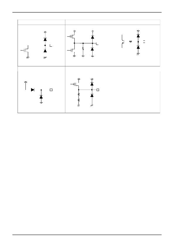
�20.� SW�
�21.� OUTH�
�22.� CS�
�Vcc�
�BOOT�
�BOOT�
�Vcc�
�5K�
�CS�
�SW�
�100K�
�OUTH�
�23.� BOOT�
�VREG�
�BOOT�
�SW�
�24.� VREG�
�SW�
�VREG�
�SW�
�Vcc�
�VREG�
�205K�
�100K�
�SW�
�*All� values� typical.�
�●� Notes� for� use�
�1.� Absolute� maximum� ratings�
�We� are� careful� enough� for� quality� control� about� this� IC.� So,� there� is� no� problem� under� normal� operation,� excluding� that� it�
�exceeds� the� absolute� maximum� ratings.� However,� this� IC� might� be� destroyed� when� the� absolute� maximum� ratings,� such�
�as� impressed� voltages� or� the� operating� temperature� range� (Topr)� is� exceeded,� and� whether� the� destruction� is� short� circuit�
�mode� or� open� circuit� mode� cannot� be� specified.� Please� take� into� consideration� the� physical� countermeasures� for� safety,�
�such� as� fusing,� if� a� particular� mode� that� exceeds� the� absolute� maximum� rating� is� assumed.�
�2.� Reverse� polarity� connection�
�Connecting� the� power� line� to� the� IC� in� reverse� polarity� (from� that� recommended)� will� damage� the� part.� Please� utilize� the�
�direction� protection� device� as� a� diode� in� the� supply� line.�
�3.� Power� supply� line�
�Due� to� return� of� regenerative� current� by� reverse� electromotive� force,� using� electrolytic� and� ceramic� suppress� filter�
�capacitors� (0.1μF)� close� to� the� IC� power� input� terminals� (Vcc� and� GND)� are� recommended.� Please� note� the� electrolytic�
�capacitor� value� decreases� at� lower� temperatures� and� examine� to� dispense� physical� measures� for� safety.�
�And,� for� ICs� with� more� than� one� power� supply,� it� is� possible� that� rush� current� may� flow� instantaneously� due� to� the� internal�
�powering� sequence� and� delays.� Therefore,� give� special� consideration� to� power� coupling� capacitance,� width� of� power�
�wiring,� GND� wiring,� and� routing� of� wiring.� Please� make� the� power� supply� lines� (where� large� current� flow)� wide� enough� to�
�reduce� the� resistance� of� the� power� supply� patterns,� because� the� resistance� of� power� supply� pattern� might� influence� the�
�usual� operation.�
�4.� GND� line�
�The� ground� line� is� where� the� lowest� potential� and� transient� voltages� are� connected� to� the� IC.�
�5.� Thermal� design�
�Do� not� exceed� the� power� dissipation� (Pd)� of� the� package� specification� rating� under� actual� operation,� and� please� design�
�enough� temperature� margins.�
�6.� Short� circuit� mode� between� terminals� and� wrong� mounting�
�Do� not� mount� the� IC� in� the� wrong� direction� and� be� careful� about� the� reverse-connection� of� the� power� connector.�
�Moreover,� this� IC� might� be� destroyed� when� the� dust� short� the� terminals� between� them� or� power� supply,� GND.�
�www.rohm.com�
�?� 2010� ROHM� Co.,� Ltd.� All� rights� reserved.�
�20/22�
�2011.08� -� Rev.C�
�发布紧急采购,3分钟左右您将得到回复。
相关PDF资料
BD8119FM-ME2
IC WHITE LED DVR PWM 28-HSOP
BD82103GWL-E2
IC LED DRVR WHITE BCKLGT 11-UCSP
BD9206EFV-E2
IC LED DRIVER 6V LCD 20HTSSOP
BD9207FPS-E2
IC LED DVR STEPDWN 1.5A TO252S-5
BH-14E_TI-20T_CTI
ADAPTER PIN CONVERTER 14-20 PIN
BH-20E_CTI-60T_TI
ADAPTER PIN CONVERTER 20-60 PIN
BH-ADP-ISO20
ISOLATION ADAPTER 20-PIN TI JTAG
BH-GANG2000
GANG2000 PROGRAMMER TI 32BIT MCU
相关代理商/技术参数
BD8113EFV
制造商:ROHM 制造商全称:Rohm 功能描述:White Backlight LED Driver for Medium to Large LCD Panels (Switching Regulator Type)
BD8113EFV_11
制造商:ROHM 制造商全称:Rohm 功能描述:White Backlight LED Driver for Medium to Large LCD Panels (Switching Regulator Type)
BD8113EFV-E2
功能描述:LED照明驱动器 IC LED DRIVER RoHS:否 制造商:STMicroelectronics 输入电压:11.5 V to 23 V 工作频率: 最大电源电流:1.7 mA 输出电流: 最大工作温度: 安装风格:SMD/SMT 封装 / 箱体:SO-16N
BD8115F-M
制造商:ROHM 制造商全称:Rohm 功能描述:LED Driver IC
BD8115F-MTE2
功能描述:LED照明驱动器 Auto Grade LED Drvr RoHS:否 制造商:STMicroelectronics 输入电压:11.5 V to 23 V 工作频率: 最大电源电流:1.7 mA 输出电流: 最大工作温度: 安装风格:SMD/SMT 封装 / 箱体:SO-16N
BD8115FP-MTE2
制造商:ROHM 制造商全称:Rohm 功能描述:LED Driver IC
BD8115HFP-MTTR
制造商:ROHM 制造商全称:Rohm 功能描述:LED Driver IC
BD8118FM
制造商:ROHM 制造商全称:Rohm 功能描述:Silicon Monolithic Integrated Circuit